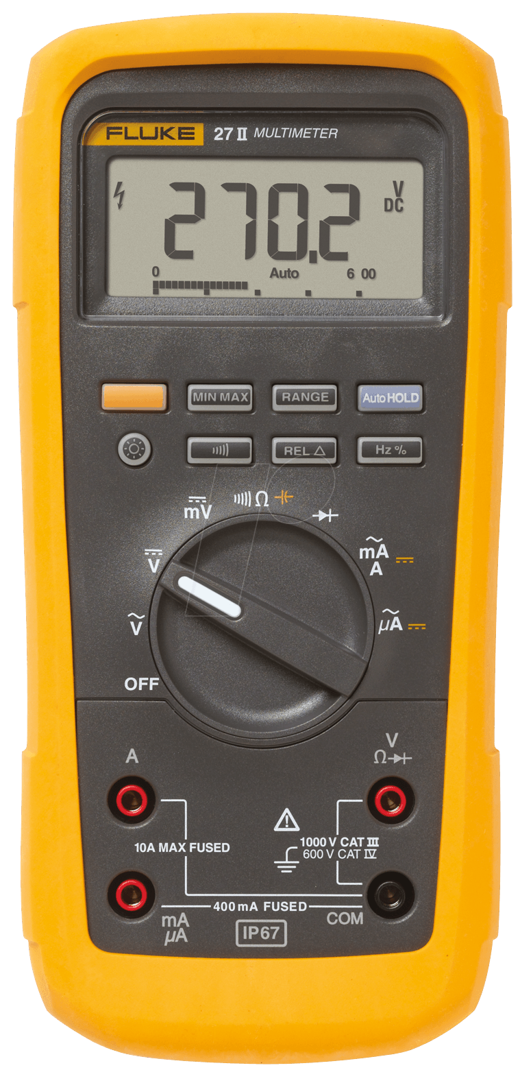
Manual For Fluke 75 Series Ii Multimeter

Books.google.co.th - Well over 9,000 Total Pages - Just a SAMPLE of what is included:CALIBRATION PROCEDURE FOR DIAL INDICATING PRESSURE GAGESCALIBRATION PROCEDURE FOR VERNIER CALIPERS, TYPE 1 CLASSES 1, 2 3 7 PagesCALIBRATION PROCEDURE FOR TORQUE WRENCH, RAYMOND ENGINEERING, I MODEL PD 730 8 PagesCALIBRATION PROCEDURE FOR. Manuals Combined: Over 300 U.S.
Unless otherwise indicated. And 23 and 21 Series II Multimeters. Beziehen Informationen in diesem Handbuch erwahnten Modelle.75. Manual applies to all models. Les precedes d'entretien de base et les donnees techniques concernant les multimetres Fluke 77. And specifications for the Fluke 77. Les renseignements toumls dans ce manuel s'appliquent.
- We have 3 Fluke 75 manuals available for free PDF download: Service Manual. Brand: Fluke Category: Multimeter Size: 5.89 MB.
- No information is available for this page.Learn why.


Army Operator and Calibration Manuals For The Multimeter, Oscilloscope, Voltimeter, Microwave Pulse Counter, Gage, Caliper & Calibrator.
® 77/75/23/21 Series III Multimeter Instruction Sheet W Read First: Safety Information ∙ Never use the meter if the meter or test leads look damaged. ∙ Be sure the test leads and switch are in the correct position for the desired measurement. ∙ Never measure resistance in a circuit when power is applied. ∙ Never touch the probes to a voltage source when the test leads are plugged into the 10 A or 300 mA input jack. ∙ Never apply more than the rated voltage between any input jack and earth ground. ∙ Be careful when working with voltages above 60 V dc or 30 V ac rms. Such voltages pose a shock hazard.
∙ Keep your fingers behind the finger guards on the test probes when making measurements. WWarning To avoid false readings, which could lead to possible electric shock or personal injury, replace the battery as soon as the battery indicator ( M) appears. Continuity Test ( R ) RANGE RANGE CAT CAT CAT CAT + + hc8f.eps If continuity exists (resistance. Service and Parts To contact Fluke, call one of the following telephone numbers: USA and Canada: 1-888-99-FLUKE (1-888-993-5853)Europe: +31 402-678-200 Japan: +81-3-3434-0181Singapore: +65-.-276-6196 Anywhere in the world: +1-425-356-5500 Or, visit Fluke’s Web site at www.fluke.com.
Item Description Fluke Quan. PN BT1 Battery, 9 V, NEDA 1604/IEC 6F22, or 696534 1 NEDA 1604A/IEC 6LR61 614487 Models 21/75: F1.
Fuse, F630 mA, 250 V, Min Interrupt 740670 1 Rating 1500 A or IEC 127-1 F2. Fuse, F11 A, 1000 VAC/DC, 943118 1 Min Interrupt Rating 17 kA Models 23/77: F1.
Manual For Fluke 75 Series Ii Multimeter Symbols
Fuse, F44/100 A, 1000 VAC/DC, 943121 1 Min Interrupt Rating 10 kA F2. Fuse, F11 A, 1000 VAC/DC, 943118 1 Min Interrupt Rating 17 kA. For safety, use exact replacement Specifications Accuracy is specified for a period of one year after calibration, at 18 °C to 28 °C (64 °F to 82 °F) with relative humidity to 90%. AC conversions are ac-coupled,average responding, and calibrated to the RMS value of a sine wave input. Accuracy specifications are given as: ±(% of reading + number of least significant digits) Maximum Voltage Between Rated voltage any Terminal and Earth Ground Display Digital: 3,200 counts, updates 2.5/sec Analog: 31 segments, updates 25/sec Response Time of Digital V ac 28 °C).
Total accuracy = Specified accuracy + 0.1% of range. 0% to 90% (0 °C to 35 °C) 0% to 70% (35 °C to 50 °C) 0% to 80% (0 °C to 35 °C) 0% to 70% (35 °C to 50 °C) Operating: 2000 meters Storage: 12,000 meters 9 V NEDA 1604 or 6F22 or 006P, or NEDA 1604A or 6LR61 2000 hrs typical with alkaline 1600 hrs typical with carbon zinc 4096 Hz per MIL-T-PRF28800F Class III, Sinusoidal, Non Operating 3.7 cm x 8.9 - 7.8 cm x 19 cm (1.5 in x 3.5 - 3.1 in x 7.49 in) 365 g (12.9 oz) Models 21/75 Series III: 600 V CAT III, Models 23/77 Series III: 600 V CAT III and 1000 V CAT II per ANSI/ISA S,EN 61010-1:1993, CSA C22.2 No 1010.1-92,UL 3111-1. Function Range Accuracy L 3.200 V, 32.00 V, 320.0 V ±(0.3%+1) 600 V (21/75), 1000 V (23/77) ±(0.4%+1) m L 320.0 mV ±(0.3%+1) K (45 to 500 Hz, 3.200 V, 32.00 V, 320.0 V ±(2%+2) 3.2 V range. Other 600 V (21/75), 1000 V (23/77) ±(2%+2) ranges 45 to 1 kHz) e 21/75: 320.0 Ω ±(0.5%+2) 3200 Ω, 32.00 k Ω, ±(0.5%+1) 320.0 k Ω 3.200 M Ω ±(0.5%+1) 32.00 M Ω ±(2%+1) 23/77: 320.0 Ω ±(0.5%+3) 3200 Ω, 32.00 k Ω, ±(0.5%+1) 320.0 k Ω 3.200 M Ω ±(0.5%+1) 32.00 M Ω ±(2%+1) G R 2.0 V ±(1% typical) Function Range Accuracy Burden Voltage (typical)? (45 Hz 32.00 mA, 320.0 mA ±(2.5%+2) 6 mV/mA to 1 kHz) 10.00 A.
±(2.5%+2) 50 mV/A A 32.00 mA, 320.0 mA ±(1.5%+2) 6 mV/mA 10.00 A. ±(1.5%+2) 50 mV/A. 10 A continuous, 20 A for 30 seconds maximum. Overload protection for all functions and ranges: Rated voltage.
Function Input Impedance (Nominal) L, mL, K 10 M Ω, 120 dB at dc, 60 dB at 50 Hz or 60 Hz 50 Hz, or 60 Hz K 60 dB dc to 60 Hz Open Circuit Test Full Scale Voltage Voltage To 3.2 M Ω 32 M Ω e.